
+1 877 930 0717 (NA Toll Free) Langley, BC, Canada DC Power Engineering Since 1986
0%

Reliable communication depends on stable power, especially when radio units operate through storms, remote travel, or extended outages. The 2026 Best Land Mobile Radio DC Power Supply Types guide examines practical options for public safety, transportation, utilities, industrial teams, and field communications. It considers AC-to-DC supplies, battery-backed systems, modular rectifiers, DC-DC converters, and solar-assisted configurations.

Each type serves a different operating reality. A 12-volt supply may suit a vehicle installation, while a 24- or 48-volt system can support larger sites. Clean output matters because voltage ripple may cause noise, resets, or shortened equipment life. Battery charging performance matters too. A supply that keeps radios online for ten minutes may fail during a four-hour outage. Small details matter.

Selection should reflect measured load, startup current, ambient temperature, battery capacity, and future expansion. Redundant modules can keep a radio site operating when one component fails. Surge protection and electromagnetic compatibility also deserve careful testing. Manufacturer specifications provide a foundation, but field experience often reveals weaknesses hidden by laboratory figures. A neat data sheet can still mislead.

This review compares efficiency, maintenance demands, protection features, installation flexibility, and total ownership cost. It also considers cabinet space, ventilation, wiring distance, and service access. The strongest choice is not always the most powerful model. Sometimes, simpler is safer. Readers should verify local electrical requirements and equipment documentation before deployment, because operating conditions vary more than product brochures suggest.
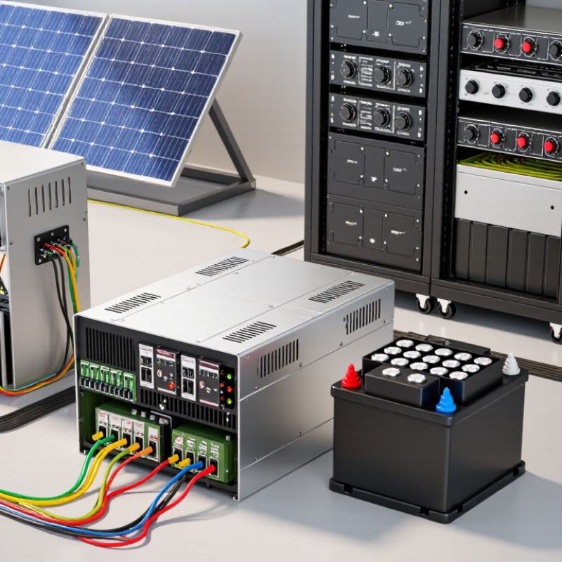
2026 Best Land Mobile Radio DC Power Supply Types

Understanding DC Power Requirements in Land Mobile Radio Systems

2026 Best Land Mobile Radio DC Power Supply Types

Land mobile radio systems depend on stable direct current during routine dispatch and emergency communication. Most installations use a nominal 12, 24, or 48-volt DC bus. The correct voltage must match the radio, accessories, battery bank, and cable length. A small voltage drop can cause weak transmission, resets, or distorted audio.

Float-type supplies are common where batteries provide standby support. They continuously maintain the battery while feeding the radio load. Switching supplies are often lighter and more efficient, especially in vehicles or compact shelters. However, their electrical noise requires careful filtering and grounding. Modular DC systems offer useful redundancy. One failed module may not interrupt service, but only when the remaining capacity is properly calculated.

Engineers should measure peak transmit current, not just average consumption. A radio drawing 8 amperes during transmission may need far less in receive mode. Battery capacity should cover the required backup period, temperature effects, aging, and future equipment. Short, thick conductors reduce loss. Use protection close to the power source. Test the system under realistic transmit conditions.

Field experience shows that paperwork can hide practical problems. A supply may pass a bench test yet fail after long cable runs. I have found loose terminals, undersized fuses, and poorly ventilated cabinets affecting reliability. The calculation is not always wrong, but its assumptions may be. Record voltage readings at the radio during peak load, then review them after installation changes.

Linear and Switching DC Power Supply Types for LMR Applications

2026 Best Land Mobile Radio DC Power Supply Types

Linear and switching DC power supplies serve different needs in land mobile radio systems. Linear supplies are valued for low electrical noise and predictable output. They can suit sensitive base stations, control rooms, and testing benches. However, their transformers run warm and waste more energy. A 13.8 V linear unit may require clear airflow, especially inside a crowded equipment cabinet. Heat accumulates quickly.

Switching supplies are smaller, lighter, and usually more efficient. They handle continuous duty well in vehicle fleets, dispatch centers, and remote repeater shelters. Modern designs can provide stable voltage during changing radio loads. Still, switching circuits may produce ripple or electromagnetic interference if filtering is weak. That matters near receivers. Cable routing matters too. Keep DC leads short, secure, and separated from antenna feeders where practical.

A reliable LMR installation often combines a switching supply with battery backup and careful protection. Check voltage tolerance, current headroom, surge behavior, grounding, and operating temperature. A supply rated exactly for the radio may struggle during transmit bursts. Leave practical margin. It is easy to focus on efficiency and overlook maintenance access. Dust, loose terminals, and aging batteries can undermine excellent specifications. Field conditions are less tidy than test rooms. A final load test under real transmit conditions remains one of the most useful checks.

Comparing Regulated, Unregulated, and Redundant Power Supply Designs

2026 Best Land Mobile Radio DC Power Supply Types

Regulated DC supplies keep voltage stable during radio transmit bursts and changing battery conditions. That stability protects sensitive control boards and reduces audio distortion. Unregulated designs are simpler, cheaper, and easier to service. However, their output can fall sharply under load. A portable repeater may tolerate this variation. A continuously operated dispatch site usually should not.

Redundant supplies use parallel modules, separate feeds, or N+1 capacity. One module can be removed while the radio remains online. That matters during battery replacement, thermal alarms, or unexpected module failure. Uptime Institute’s 2024 Global Data Center Survey reported that 53% of respondents experienced an outage within three years. The survey covers data centers, not LMR sites, but its reliability signal is relevant. Power design deserves the same discipline.

Field design reviews often reveal an uncomfortable detail: redundancy does not fix poor sizing. Two weak supplies still create a weak system. Engineers should measure transmitter peak current, battery aging, cable voltage drop, and cabinet temperature. Monitoring should record voltage, current, battery status, and module alarms. Regulated units suit demanding fixed stations. Unregulated units may fit basic, cost-sensitive installations. Redundant regulated systems offer stronger continuity, but they add wiring, controls, and failure points. That trade-off is easy to underestimate.

2026 Best Land Mobile Radio DC Power Supply Types - Comparing Regulated, Unregulated, and Redundant Power Supply Designs

Evaluation Dimension Regulated DC Power Supply Unregulated DC Power Supply Redundant DC Power Supply Design
Primary operating principle Maintains a controlled DC output using feedback regulation, typically through a switching or linear regulator. Uses rectification, filtering, and a transformer or converter without closed-loop output regulation. Uses two or more power modules, generally operating in parallel or load-sharing mode, so one module can support the load if another fails.
Typical LMR output voltage 13.8 VDC nominal for 12 V vehicle-radio systems; other common configurations include 24 VDC and 48 VDC. Often rated around 13.8 VDC, but actual voltage changes with input voltage, load, temperature, and battery condition. Commonly 13.8 VDC for radio equipment, with the output maintained by independent regulated modules and a shared distribution bus.
Output voltage accuracy Typically within approximately ±1% to ±2%, depending on design, operating range, and calibration. Usually not tightly specified; voltage may vary several percent or more between no-load and full-load conditions. Typically within approximately ±1% to ±2% during normal operation, subject to module matching and control architecture.
Voltage regulation under load Good; feedback control compensates for radio transmit bursts and changing load demand. Limited; voltage typically sags as current increases and rises when the load decreases. Good; active regulation is combined with current sharing and automatic fault isolation.
Typical continuous current range Approximately 10–100 A for single-radio, dispatch, repeater, and small communication-system applications. Approximately 5–50 A in basic installations where load variation and voltage tolerance are acceptable. Approximately 20–200 A or higher, depending on the number and capacity of installed modules.
Response to radio transmit bursts Good transient response when correctly sized; output capacitors and control loops help limit voltage droop. Moderate to poor; short-term voltage sag can occur during high-current RF transmission. Very good when modules are correctly paralleled and the system includes sufficient energy storage and current headroom.
Ripple and electrical noise Typically low ripple; well-designed switching units may be below 100 mV peak-to-peak, while filtering and installation affect the final result. May have low-frequency ripple from rectification and filtering; performance depends strongly on transformer, capacitor, and load design. Typically low ripple, but multiple switching modules may require coordinated filtering and careful grounding to prevent conducted noise.
Efficiency Approximately 80–95% for modern switching designs; linear regulated units are generally less efficient. Approximately 70–90%, depending on transformer losses, rectifier type, and operating load. Approximately 80–95% at the module level; system efficiency can decline because of load-sharing, monitoring, and standby losses.
Fault protection Commonly includes over-current, short-circuit, over-voltage, over-temperature, and input surge protection. Basic fuse or circuit-breaker protection is common; electronic current limiting and over-voltage protection may be limited. Typically includes per-module protection, OR-ing or ideal-diode isolation, alarm reporting, and automatic failed-module removal.
Continuity during a single module failure The radio system normally loses DC power unless a separate battery, backup supply, or automatic transfer arrangement is installed. The radio system normally loses DC power unless an external backup source is provided. Can maintain operation if the remaining module capacity is sufficient for the full load; this is the basis of N+1 designs.
Battery integration Often supports a DC distribution bus with a battery charger or battery backup, provided charging voltage and current are correctly configured. Can be simple to integrate, but uncontrolled voltage may be unsuitable for float charging or sensitive radio equipment. Well suited to critical DC systems with batteries, monitored charging, automatic transfer, and separate distribution protection.
Thermal management Usually requires ventilation or a fan at higher power levels; thermal derating should be checked for hot equipment rooms and vehicle enclosures. May be simpler at low power, but transformer and rectifier losses can create significant heat at higher current. Produces additional heat and requires airflow planning because multiple modules may operate simultaneously under normal conditions.
Installation complexity Low to medium; wiring, grounding, fusing, and output-voltage adjustment must be completed correctly. Low; the architecture is straightforward, but voltage variation must be accepted in the system design. Medium to high; requires module coordination, current sharing, isolation, alarm wiring, and service clearance.
Maintenance approach Periodic inspection, fan and connector checks, output-voltage verification, and replacement of the complete unit when it fails. Generally simple to service, with fuses, capacitors, rectifiers, or the complete supply requiring replacement as needed. Supports planned hot-swap or front-access module replacement when the design provides it, reducing service interruption.
Relative initial cost Medium; cost increases with higher current, power-factor correction, monitoring, and environmental ratings. Low; simple construction usually provides the lowest purchase cost for non-critical loads. High; additional modules, control circuitry, isolation, monitoring, and mechanical infrastructure increase cost.
Best-fit LMR application Mobile command vehicles, dispatch consoles, base stations, repeaters, and general-purpose radio installations requiring stable voltage. Simple, low-cost installations with tolerant equipment, limited duty cycles, and non-critical communications requirements. Public-safety dispatch, emergency communications, remote repeater sites, transportation networks, and other high-availability systems.
Main advantages Stable output, good transient performance, broad protection features, and compatibility with sensitive electronic radio equipment. Low purchase cost, simple circuitry, straightforward troubleshooting, and potentially low maintenance at modest power levels. High availability, fault isolation, serviceability, capacity expansion, and reduced risk of a single-point power failure.
Main limitations A single unit remains a single point of failure, and switching designs may require additional RF-noise filtering. Variable output voltage, weaker transient control, less predictable battery charging, and greater risk for voltage-sensitive equipment. Higher cost, larger physical footprint, greater heat output, and more complex installation and diagnostics.
Recommended design priority Select adequate continuous and peak current capacity, low ripple, correct voltage setting, and suitable transient protection. Use only when the connected radio equipment tolerates the full expected voltage range and the availability requirement is low. Use N+1 capacity where uninterrupted service is important, and verify current sharing, alarm functions, and battery-backup behavior.

Note: Values shown are representative engineering ranges for comparison. Actual performance depends on system voltage, duty cycle, ambient temperature, installation method, battery configuration, and the power supply design specification.

Selecting a 2026 LMR DC Power Supply for Performance and Reliability

Selecting a 2026 LMR DC power supply requires more than matching voltage and wattage. Radio transmitters can create sudden current peaks, while receivers need a quiet, stable output. A regulated linear supply may offer very low electrical noise, but it can produce more heat. A switching supply is usually lighter and more efficient, yet its ripple must be checked carefully. Modular systems can improve serviceability and redundancy in busy dispatch rooms.

Check the radio’s maximum transmit current, standby demand, startup surge, and future expansion needs. A practical margin of 25–30% can reduce stress during continuous operation. Battery backup should transfer smoothly, without a noticeable voltage dip. Remote alarms, temperature monitoring, overvoltage protection, and short-circuit protection also matter. Verify cooling performance at the highest expected ambient temperature, not only in a clean laboratory.

Tips: Measure ripple under real transmit loads. Confirm cable voltage drop at the rack. Use separate, protected circuits where required. Keep ventilation paths clear. Test alarms before deployment.

Do not trust the label alone. A supply rated for 30 amps may perform poorly near its limit for hours. I have seen installation plans overlook cable length, then blame the supply for radio resets. That mistake is avoidable, although field conditions can still expose assumptions. Select equipment with documented test data, traceable protection features, and service procedures that technicians can actually follow. Reliability is often decided by small details.

2026 Best Land Mobile Radio DC Power Supply Types

Selecting a 2026 LMR DC power supply for performance and reliability requires balancing efficiency, isolation, thermal behavior, serviceability, and backup capability.

The chart shows representative engineering ranges for common power-supply topologies used in LMR infrastructure. Actual efficiency depends on input voltage, output load, temperature, regulation requirements, protection features, and operating conditions.

Installation, Safety, and Maintenance Considerations for LMR Power Systems

2026 Best Land Mobile Radio DC Power Supply Types

Land mobile radio systems depend on stable DC power during routine calls and emergencies. Common options include regulated switch-mode supplies, linear supplies, and battery-backed DC systems.

Switch-mode units usually save space and energy. Linear units can offer low electrical noise, but they may produce more heat. Battery-backed systems maintain communication during short utility failures.

Selection should match radio load, backup time, ambient temperature, and future expansion.

Do not size a supply from the radio’s idle rating. Measure transmit current and startup demand.

Installation quality affects safety and radio performance. Place the supply in a dry, ventilated enclosure with clear airflow around heat-producing components.

Use correctly rated fuses near the DC source, and protect every branch circuit separately. Confirm polarity before energizing the equipment. A reversed connection can damage sensitive radio electronics within seconds.

Bond exposed metalwork and grounding conductors according to local electrical requirements. Keep power cables separated from high-current transmit wiring where practical. Label disconnects clearly.

Small details matter.

Maintenance should include visual checks, output-voltage testing, and inspection of terminals for looseness or corrosion. Test the system under radio transmit load, not only at idle.

Record voltage, current, temperature, and battery condition in a dated log. Replace damaged insulation immediately. Battery rooms need suitable ventilation and controlled access.

Field technicians often discover that neglected airflow causes more failures than defective components. I have seen maintenance plans overlook connector torque. That mistake deserves review.

Set reminders for load tests, filter cleaning, and battery replacement intervals.

FAQS

What is the main difference between linear and switching DC power supplies?

Linear supplies usually produce very low electrical noise. They can suit sensitive receivers and testing benches. Switching supplies are smaller, lighter, and more efficient. However, weak filtering may create ripple or interference.

When is a linear power supply a good choice?

Choose a linear supply when electrical noise must remain extremely low. It may suit a control room, base station, or laboratory bench. Expect more heat and higher energy use. Heat builds fast.

Where do switching supplies work well?

Switching supplies suit vehicle fleets, dispatch centers, and remote repeater shelters. Their compact size helps inside crowded cabinets. They also handle continuous operation efficiently. Keep airflow clear.

How much current margin should an LMR supply have?

A practical margin of 25–30% can reduce stress during operation. Check maximum transmit current, standby demand, and startup surge. A supply rated exactly for the radio may struggle during transmit bursts. Measure it.

Why should ripple be tested under transmit conditions?

Radio loads can change suddenly during transmission. Ripple may increase when the supply approaches its limit. Test the output with the radio transmitting, not only at idle. Laboratory results can look better than field results.

How should DC cables be installed?

Keep DC leads short, secure, and properly sized. Check voltage drop at the equipment rack. Separate power cables from antenna feeders where practical. Cable length is easy to underestimate.

What protection features should a reliable supply include?

Useful features include overvoltage, short-circuit, surge, and temperature protection. Remote alarms can warn technicians about failures or overheating. Battery backup should transfer without a noticeable voltage dip. Test every alarm.

What maintenance details can affect long-term reliability?

Keep ventilation paths free from dust and obstruction. Inspect terminals, cooling fans, and aging batteries. Confirm access for future servicing. Small details matter.

Conclusion

Choosing the right Land Mobile Radio DC Power supply is essential for maintaining clear communication, dependable coverage, and continuous operation in critical radio systems. This overview explains the DC power requirements of LMR equipment and compares common linear and switching power supply designs. It also examines the differences between regulated, unregulated, and redundant configurations, helping readers understand how voltage stability, efficiency, backup capability, and operating conditions affect system performance.

For 2026 installations, selecting a suitable LMR power supply requires balancing load capacity, energy efficiency, reliability, and future expansion needs. Proper installation should include correct wiring, grounding, ventilation, circuit protection, and safe battery integration. Regular inspection, testing, and maintenance can help identify declining performance before it causes service interruptions. By evaluating technical requirements and applying sound safety practices, organizations can build a resilient power system that supports reliable Land Mobile Radio communications in demanding environments.

Amelia

Amelia

Amelia is a professional marketing specialist with a strong understanding of the company’s products, market positioning, and customer needs. Through her extensive experience in content strategy, brand communication, and digital marketing, she transforms complex product information into clear,......